SCU(System Control Units)
The System Control Unit (SCU) is a cluster of sub-modules which control various system functions, including: • Reset Control (RCU) • Trap generation (TR) • System Registers for miscellaneous functions (SRU) • Watchdog Timers (WDT) • External Request handling (ERU) • Emergency Stop (ES) • Power Management Control (PMC)
The following reset request triggers are available:
Supply monitor (SWD) triggers a power-on reset (cold reset)Core voltage EVR (EVRC) monitor triggers a power-on reset (cold reset)3.3V EVR monitor triggers a power-on reset (cold reset) (If product has EVR33)Standby EVR (STBYR) monitor triggers a power-on reset (cold reset)External active low hardware “power-on” reset request trigger; PORST (can be either a warm reset or to extend a cold reset)External System Request reset trigger pins; ESR0 and ESR1 (warm reset)Safety Management Unit (SMU) alarm reset request trigger, (warm reset)Software reset (SW), (warm reset)System Timer (STMx) trigger (warm reset)Resets via the JTAG interfaceResets initiated via On-Chip Debug System (OCDS)复位请求触发源以及影响范围可以参考《英飞凌多核单片机应用技术AURIX三天入门篇》P142表格
**Power-on Reset:**上电复位 This reset results in initialization of the complete system into a defined state. A Power-on Reset also generates a Debug Reset and a System Reset and therefore also an Application Reset. (See also the section about Warm and Cold Resets) **• System Reset:**系统复位 This reset leads to an initialization into a defined state of the complete system but without a reset of the power subsystem, debug subsystem or reset configuration registers. A System Reset also generates an Application Reset. **• Debug Reset:**调试复位 This reset leads to an initialization into a defined state of the complete debug system. • Application Reset: 应用复位 This reset leads to an initialization into a defined state of the complete application system with the following parts: all peripherals, the CPUs and parts of the SCU. **• Module Resets:**外设模块复位 Module resets result in individual modules being initialized into a defined state without any impact on the rest of the system.
Warm and Cold Resets Warm Reset: A warm reset is a reset which is triggered while the system is already operational and the supplies remain stable. 系统供电稳定时,通过触发POSRT引脚便是触发热复位 Cold Reset: A “Cold Power-on Reset” is a reset which is triggered for the first time during a system power-up or in response to a temporary power failure. 引起冷复位的因素主要包括:
MCU启动,外部供电电压低于2.97VEVR33片上3.3V供电低于2.97VEVR13片上1.3V供电低于1.17V EVR33和EVR13 in PMSLE moduleSome special registers in the EVR are associated with functionality which should not be re-initialized even in the case of a temporary violation of an undervoltage monitor but only on a real power-up event. These are reset only when the supply drops below a very low threshold. The reset for these registers is described as “EVR Power-On Reset”
ESR引脚可以给外部提供一个芯片内部复位的信息,同时该引脚也可以接收外部触发使芯片复位,其功能如下:
触发复位请求触发唤醒请求复位指示输出触发Trap请求ESR引脚对应的工作模式:
输入–触发复位输出–产生复位指示输入–触发产生不可屏蔽中断NMI作为GPIO引脚输入–将系统从待机模式唤醒ESRx Input Configuration Register ESRCFGx (x=0-1) ESR Output Configuration Register ESROCFG Input/Output Control Register IOCR ESR Output Register OUT ESR Output Modification Register OMR ESR Input Register IN Pad Disable Control Register PDISC ESR Pad Driver Mode Register PDR
Reset Status Register RSTSTAT 需要查阅的时候直接搜芯片手册 Reset Configuration Register RSTCON
Application Reset Disable Register ARSTDIS Software Reset Configuration Register SWRSTCON Additional Reset Control Register RSTCON2 Reset Configuration Register 3 RSTCON3
The building blocks are: • Basic clock generation (Clock Source) 时钟源 • Clock speed up-scaling (PLLs) 时钟倍频 • Clock distribution (CCU) 时钟分配 • Individual clock configuration (Peripherals) 独立时钟配置 时钟系统的主要功能就是通过将外部时钟源倍频产生高频时钟,并以此为基础设置各个模块的不同时钟,确保各个模块工作在合理状态。 AURIX单片机时钟特点: (1)独立时钟配置 (2)100MHz备用时钟 (3)ERAY模块具有独立PLL-ERAY (4)支持2路时钟输出 (5)内部集成2路负载电容 (6)支持关键时钟监控(具体监控什么内容?)
Ceramic Resonator: 陶瓷谐振器
OSCCON
A back-up clock source is available as an alternate clock source. This clock source provides a stable but reliable clock source that can be used as clock for the system. It provides less accuracy than an external crystal or ceramic resonator. The back-up clock can not be enabled or disabled, or otherwise be controlled that could prevent it’s general operation. Therefore, no control bits are available beside selecting the backup-clock as source(CCUCON0.CLKSEL = 00B as clock source for the clock distribution and SYSPLLCON0.INSEL = 00B as clock source for the two PLLs).
The basic principle of alive monitoring is to detect that the monitored clock is toggling within a certain reference time slot generated by the diverse, observing/monitoring clock. If the monitored clock toggles, it is considered as alive.
The Clock monitor registers can be accessed by all CPUs in the system. However, it is suggested that only one CPU is used to control the clocks. As CPU0 is the active and available CPU after each reset, this is the best choice. CCUCON3 CCUCON4 通过控制寄存器CCUCON3和CCUCON4可以设置目标监控频率。
Typical CPU operating speeds are about 10 times faster (or even faster) than the speed of the used crystal as clock source. Therefore an up-scaling of the clock frequency is required. For the up-scaling two Phase Lock Loop (PLLs) are provided.
The System PLL can convert a low-frequency external clock signal to a high-speed internal clock for maximum performance. It allows the use of a wide range of input and output frequencies by varying the different divider factors. The System PLL also has fail-safe logic(失效安全逻辑) that detects degenerate (外部时钟输入异常)external clock behavior, such as abnormal frequency deviations or a total loss of the external clock. It can execute emergency actions if it loses its lock on the external clock.(具体的处理方式是向SMU发送故障报警同时CGU的输入时钟切换到Back-up Clock)
System PLL Status Register SYSPLLSTAT System PLL Configuration 0 Register SYSPLLCON0 System PLL Configuration 1 Register SYSPLLCON1 System PLL Configuration 2 Register SYSPLLCON2 寄存器详细需要查看芯片手册
The Peripheral PLL can convert a low-frequency external clock signal to a high-speed internal clock for maximum performance. It allows the use of input and output frequencies over a wide range by varying the different divider settings. The Peripheral PLL also has fail-safe logic that detects degenerate external clock behavior such as abnormal frequency deviations or a total loss of the external clock. It can execute emergency actions if it loses its lock on the external clock. The Peripheral PLL may become unlocked, due to a break of the crystal / ceramic resonator or the external clock line. In such a case, an SMU alarm event is generated.
注释:这里的DIVBY是控制寄存器的一个位
Peripheral PLL Status Register PERPLLSTAT Peripheral PLL Configuration 0 Register PERPLLCON0 Peripheral PLL Configuration 1 Register PERPLLCON1
Using the first two parts of the Clock System, all root clocks the system relies on for operation are defined. In the following, these root clocks need to be individually adapted in frequency (divided) and distributed to all the MCU’s modules, CPUs and blocks. This is done with focus on performance and power consumption optimization.
For clock distribution, the system is split into several sub-clock domains where the clock speed could be configured individually. There are also limitation for each sub-clock domain derived out of the internal interfaces.
Each sub-clock domain defines a logical unit from a clocking perspective point of view. The clock distribution is done via the Clock Control Unit (CCU). The CCU receives the clocks that are created by the two PLLs (fPLL0 and fPLL1/2), the back-up clock fBack, and fOSC0. These clocks are either forwarded directly or divided in order to supply the sub-clock domains.
CCU控制寄存器内部其实就是包含的针对不同模块的DIV因子,比如所GTM模块的频率: 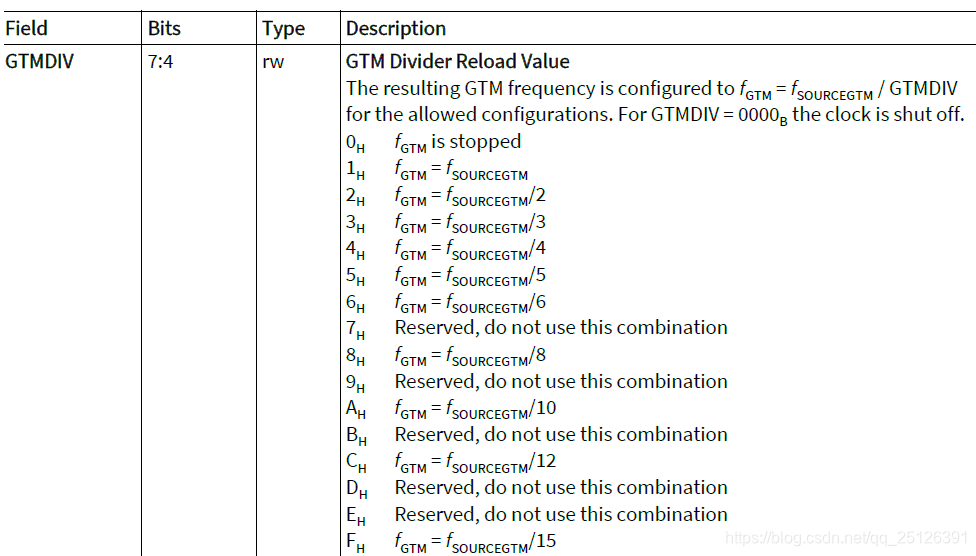 feature which can protect critical registers from accidental writes.
安全看门狗是独立于CPU看门狗的系统级看门狗,可以提供给对于关键寄存器的写保护,如果使能,且没有在用户规定的时间内喂狗,就会产生SMU报警,看门狗溢出的响应可以通过SMU模块配置。
CPU看门狗是对对应的CPU关键寄存器的写保护,如果使能,且没有在用户规定的时间内喂狗,就会产生SMU报警,看门狗溢出的响应可以通过SMU模块配置。
ENDINIT的主要功能是对关键寄存器进行写保护机制,避免对关键寄存器进行无意的修改。 每个WDT寄存器都存在ENDINIT位,通过对ENDINIT可以判断是否能够进行写保护,只有在ENDINIT=0且管理员有效的情况下,才能进行写操作。 看门狗的访问保护机制如下:
如果需要修改寄存器WDTxCON0,就必须写入正确的密码对其进行解锁,解锁寄存器需要的密码由寄存器WDTCON0和WDTCON1中的位加上一下标志位组合而成。 有关更多的密码设置需要参考芯片手册
只有在设置锁定位的情况下才会执行校验访问。该检测可以用于看门狗服务之间的校验点,可用于任务序列或者执行时间的检测。
成功解锁寄存器之后,才可以对WDTxCON0进行写访问修改,修改结束之后,WDTxCON0.LCK会重新置位,再次锁住寄存器,要想修改需要再次进行有效的密码访问。
If write access to Endinit-protected registers is required during run time, write access can be temporarily reenabled for a limited time period. Two options are provided: • Re-enable access to ENDINIT-protected registers with a WDT refresh • Re-enable access to ENDINIT-protected registers without a WDT refresh For debugging support the Cerberus module can override all the ENDINIT controls of all WDTs to ease the debug flow. If bit CBS_OSTATE.ENIDIS is set all ENDINIT protection is disabled independent of the current status configured by the WDTs. If CBS_OSTATE.ENIDIS is cleared the complete control is within the WDTs.
后续更新
Safety WDT Control Register 0 WDTSCON0 CPUy WDT Control Register 0 WDTCPUyCON0 (y=0-5) Safety WDT Control Register 1 WDTSCON1 CPUy WDT Control Register 1 WDTCPUyCON1 (y=0-5) Safety WDT Status Register WDTSSR CPUy WDT Status Register WDTCPUySR (y=0-5) ENDINIT Global Control Register 0 EICON0 ENDINIT Global Control Register 1 EICON1 ENDINIT Timeout Counter Status Register EISR Safety ENDINIT Control Register 0 SEICON0 Safety ENDINIT Control Register 1 SEICON1 Safety ENDINIT Timeout Status Register SEISR